Brand
ARCO

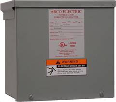
The HCMC Series capacitor design is used in applications where the total harmonic distortion levels within the plant or facility are at a level which is detrimental to the operational life of the power factor correction equipment.
DESCRIPTION
General
Construction
Capacitor Cell Design
Capacitor Losses
Tuning Filter Reactors
Electrical Characteristics
Wiring Cable Insulation
Fuse Protection & Indicator Lights (Optional ?? Add Suffix Letter ??L? to Catalog Number)
WARRANTY